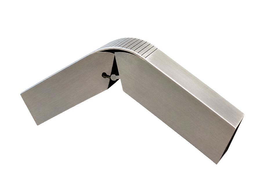
Tube + Profile Processing
Precision Tube
Precision Tube
Laser Cutting
Integrated cutting, holes, slots, notches, and joint preparation for tube components that fit together accurately and move faster into welding and assembly.
Up to 20 ftTube Length
Up to 6 inMaximum Diameter
Multiple ProfilesRound, Square, Rectangular
3 MaterialsCarbon, Stainless, Aluminum
Final capability depends on profile size, wall thickness, material, straightness, and feature geometry.
Profile Geometry
More than tube cut to length.
We review the full cross-section, wall thickness, length, and feature geometry before confirming compatibility.
Square tube
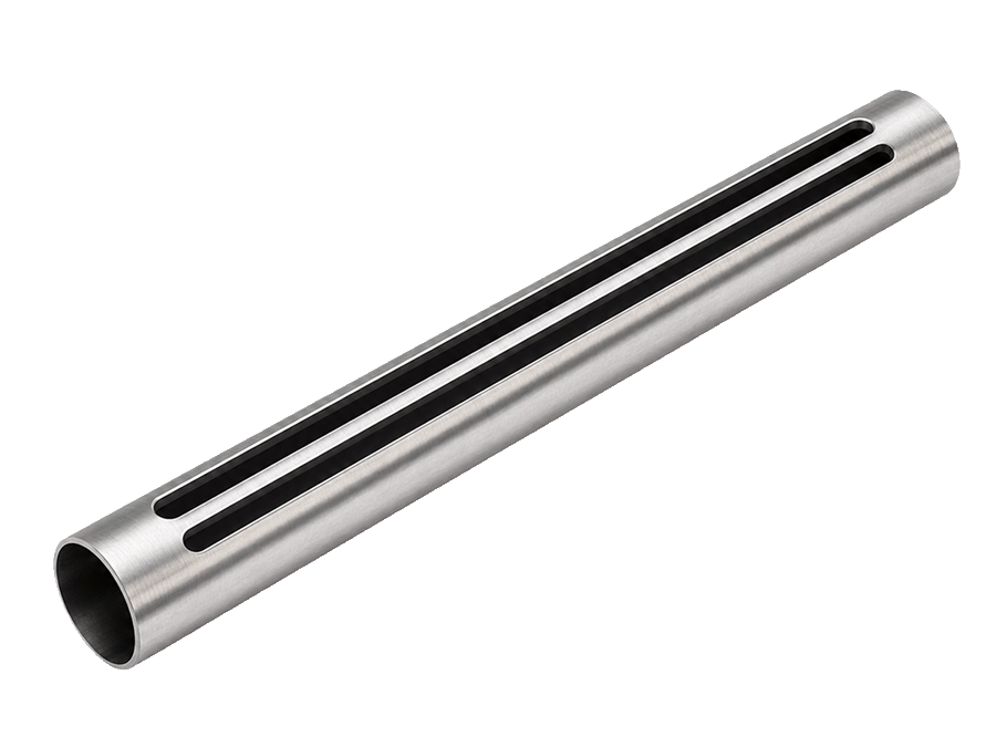
Rectangular tube
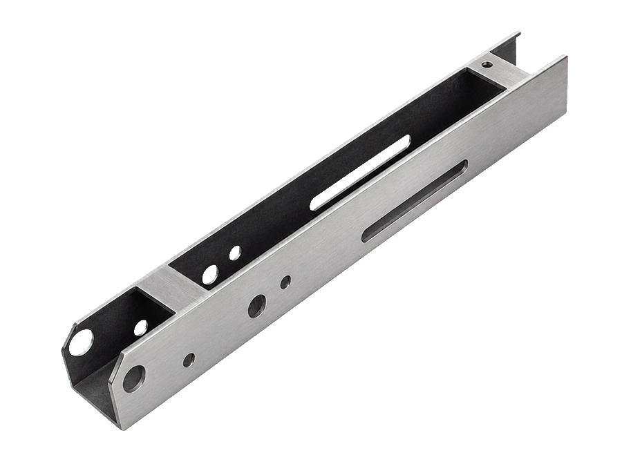
Angle and channel by review
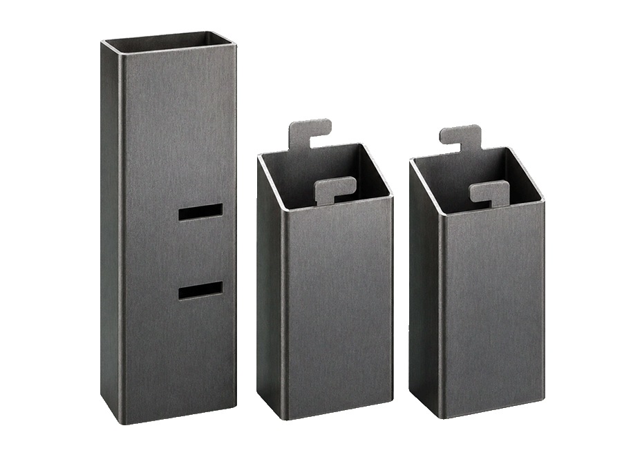
Selected structural profiles
One Controlled Process
One setup can replace multiple separate operations.
By combining operations on one CNC-controlled system, tube laser cutting can reduce manual layout, secondary drilling, saw variation, and fit-up work.
- 01
Load profile
Confirm section, seam location, straightness, and stock condition.
- 02
Cut to length
Produce controlled end locations directly from the programmed geometry.
- 03
Add holes and slots
Integrate fastener, access, and locating geometry in the same setup.
- 04
Create notches and tabs
Prepare self-locating interfaces and assembly features before welding.
- 05
Mark orientation
Add practical reference marks where the project and process allow.
- 06
Deliver assembly-ready parts
Move components into fixtures, welding, or final fabrication with less handling.
Integrated Features
Geometry cut directly into the profile.
Feature suitability depends on profile access, wall thickness, seam position, section size, and proximity to the tube ends.
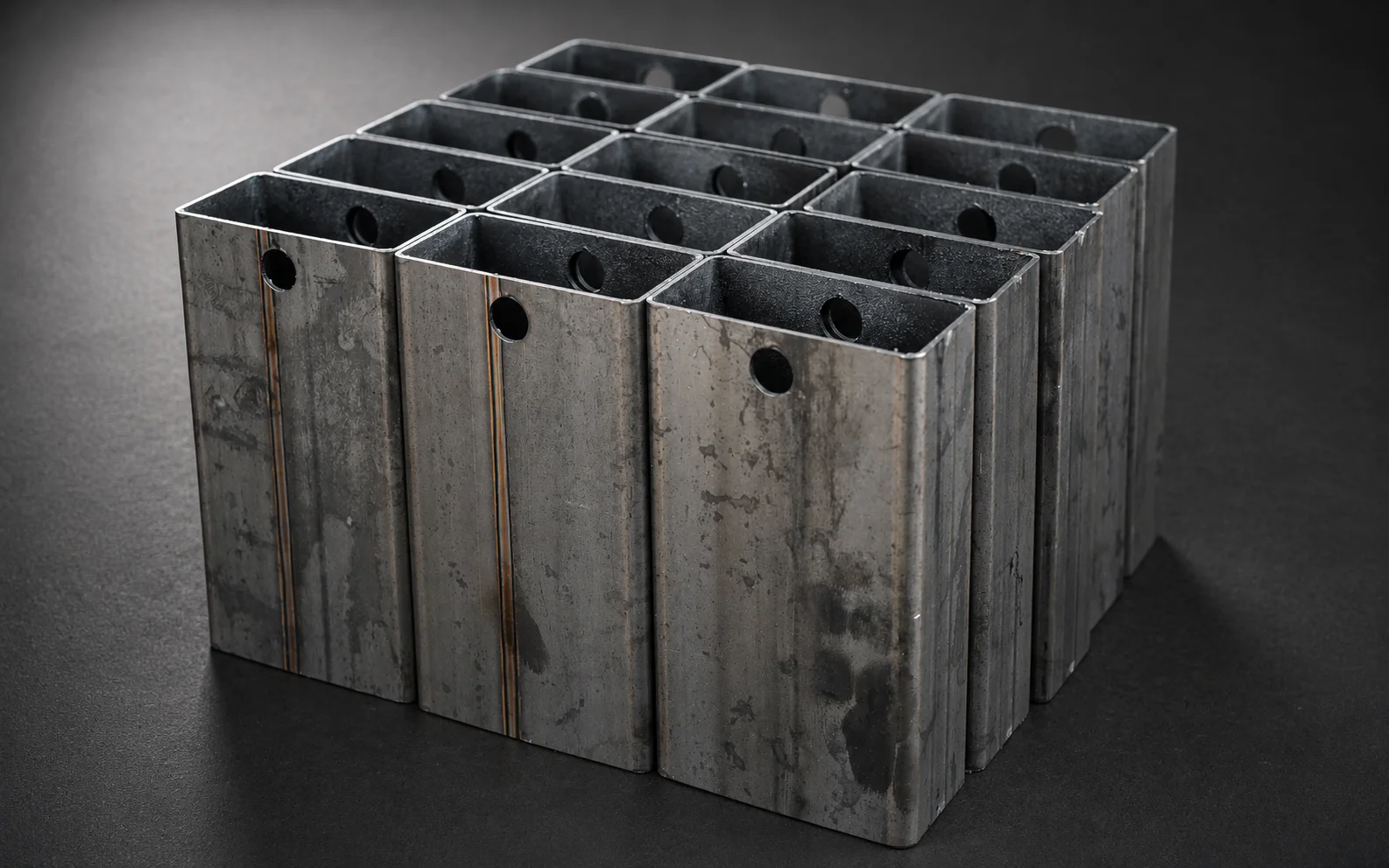
01
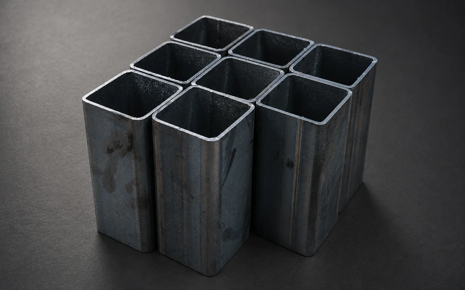
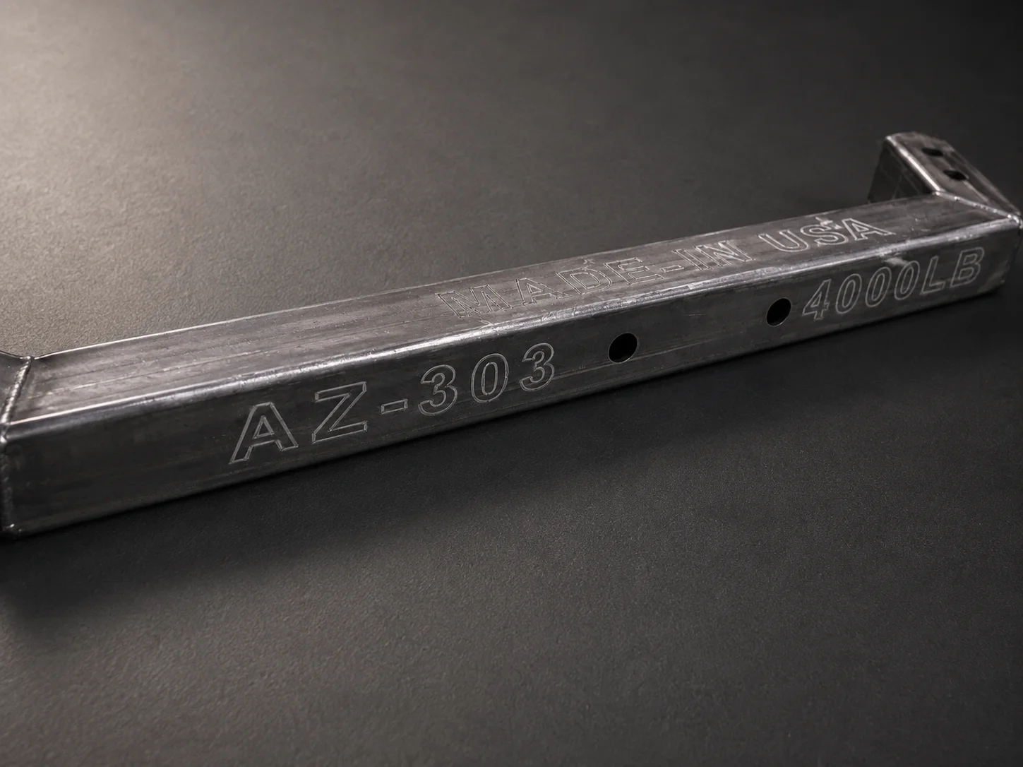
Holes and bolt patterns
Fastener, access, and mounting geometry located directly from the CNC model.
02
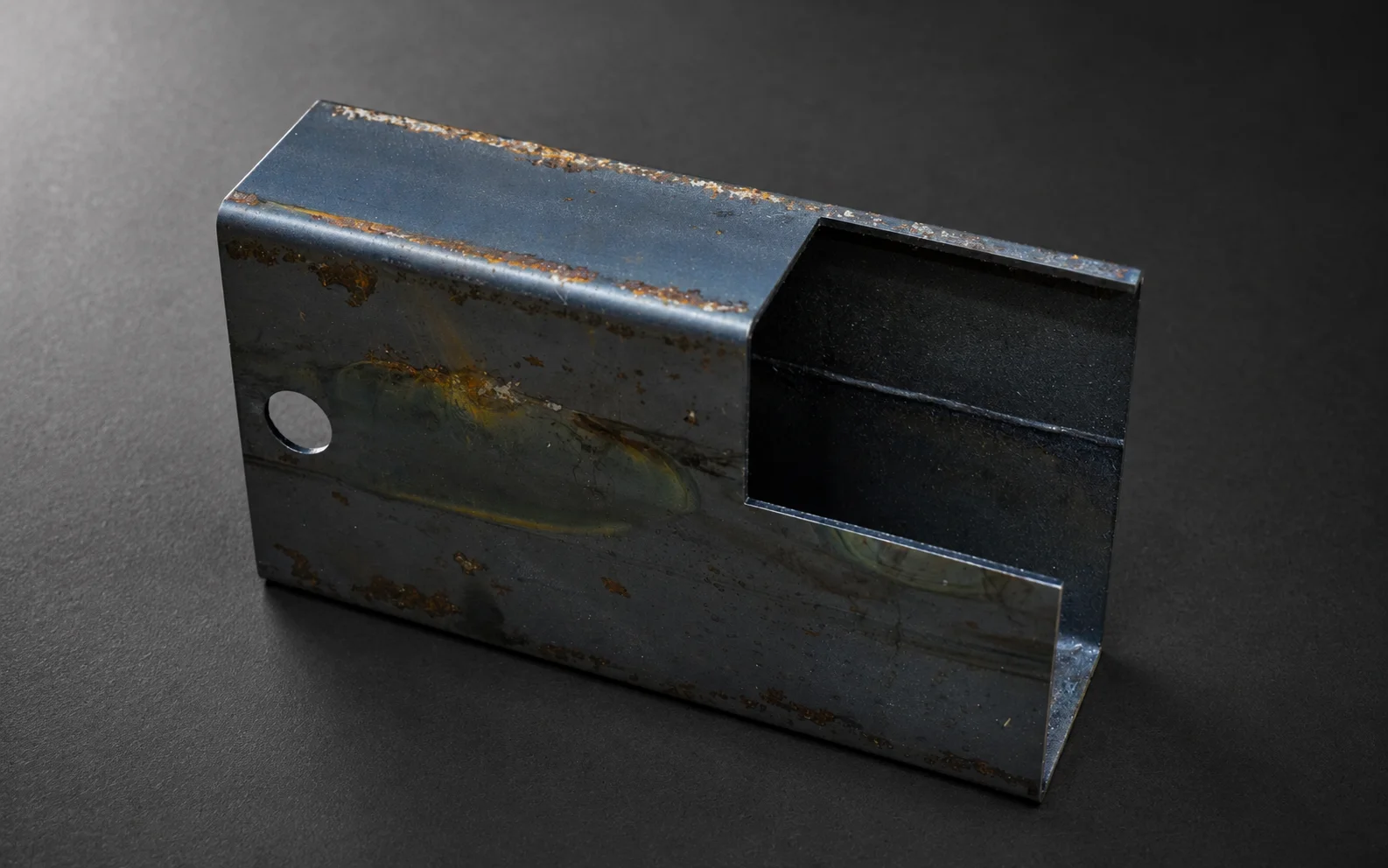
Slots and locating features
Controlled openings that support positioning, adjustment, and repeatable assembly.
03
Tabs and self-fixturing joints
Geometry designed to reduce measuring and make fit-up more repeatable.
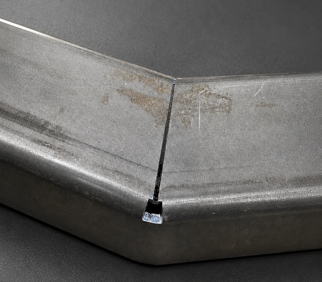
04
Fish-mouth and saddle notches
Profile intersections prepared for cleaner contact and controlled joint geometry.
05
Miters and angled end cuts
End geometry prepared directly in the profile where machine access permits.
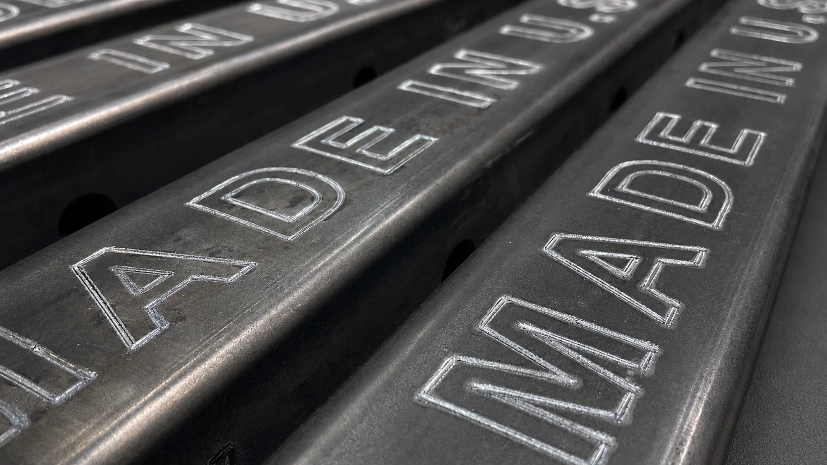
06
Part marks and references
Orientation and identification marks may be added when suitable for the material and finish.
Designed for Fit-Up
Better part definition before the first weld.
Integrated tabs, slots, notches, and reference features can reduce manual measurement and improve alignment during fit-up. Parts arrive with the intended geometry already built into the profile.
01Faster positioning
02More repeatable joints
03Reduced drilling and saw work
04Cleaner transition into welding fixtures
Applications
Built for frames, structures, and assemblies.
Tube laser cutting is most valuable when profile geometry must support fit-up, repeatability, and downstream fabrication.
Machine bases and frames
Controlled members for industrial equipment and fabricated structures.
Guards and equipment structures
Repeatable holes, slots, and end features for production assemblies.
Racks and handling systems
Profiles prepared for fixtures, casters, brackets, and connection points.
Furniture and architectural frames
Clean, defined geometry for visible structures and repeat builds.
Automation cells and supports
Integrated access and locating features for controls and equipment mounting.
Welded production assemblies
Components cut to move efficiently into fixturing and welding.
Materials + Compatibility
Profile capability is reviewed, not assumed.
Carbon Steel
Frames, structures, equipment, and production weldments.
Stainless Steel
Food equipment, marine products, architectural components, and corrosion-resistant assemblies.
Aluminum
Lightweight frames, enclosures, fixtures, and product structures.
Technical Specifications
Tube processing at a glance.
- Maximum profile length
- Up to 20 ft*
- Maximum profile diameter
- Up to 6 in*
- Common profiles
- Round, square, rectangular
- Additional profiles
- Angle, channel, and selected structural sections by review
- Materials
- Carbon steel, stainless steel, aluminum
- Integrated features
- Holes, slots, tabs, notches, miters, and end profiles
- Typical quantities
- Prototype through production
- Downstream services
- Laser welding and fabrication
- Recommended design input
- 3D model or dimensioned drawing plus material, wall, and quantity
*Maximum length and section size depend on profile geometry, wall thickness, material, loading conditions, and part features.
Featured Tube Work
View All Tube Projects
Real profile-cut components.
Loading featured tube work…
Design Guidance
Send the geometry that defines the complete profile.
A full 3D model is preferred for complex tube features, but dimensioned drawings and supporting files can also communicate the requirement.
Upload tube drawings- 01
Identify profile and outside dimensions
State whether the part is round, square, rectangular, or another reviewed section.
- 02
Provide wall thickness and material grade
Include alloy or grade when it affects performance, welding, or finish.
- 03
State overall cut length and quantity
Separate prototype requirements from expected repeat production when applicable.
- 04
Show all holes, notches, and orientation
STEP is preferred for full 3D geometry; use PDF notes for tolerances, seam orientation, and critical dimensions.
Frequently Asked Questions
Tube cutting questions, answered directly.
Our common profiles are round, square, and rectangular tube. Angle, channel,
and selected structural sections may also be possible after reviewing the section, wall thickness,
material, and required geometry.
The system can process profiles up to 20 feet in length, subject to profile
geometry, wall thickness, straightness, loading conditions, and the location of required features.
Maximum diameter is up to 6 inches. Final compatibility depends on the exact
cross-section, wall thickness, material, and part geometry.
Yes. Holes, slots, access openings, locating features, and many end profiles
can be integrated into the same CNC-controlled operation when the profile provides suitable access.
Fish-mouth, saddle, notch, miter, and angled end geometry can often be
produced directly. We confirm the exact intersection and machine access after reviewing the model or
drawing.
Yes. AZ-CNC also provides laser and MIG welding. Integrated locating features
can be designed to improve fit-up and help move tube components efficiently into welding fixtures.
STEP is preferred for complete 3D tube geometry. A dimensioned PDF should
include profile size, wall thickness, material, tolerances, seam orientation when important, and all
required cut features.
Customer-supplied material may be considered after review. We need to confirm
section consistency, material identification, straightness, seam location, surface condition, and usable
stock length.
From Profile to Assembly
Send us the
Send us the
tube geometry.
Include the profile size, wall thickness, material, length, quantity, and all required cut features. We’ll review the process and confirm the next step.